Evershed & Vignoles Battery Megger Testers
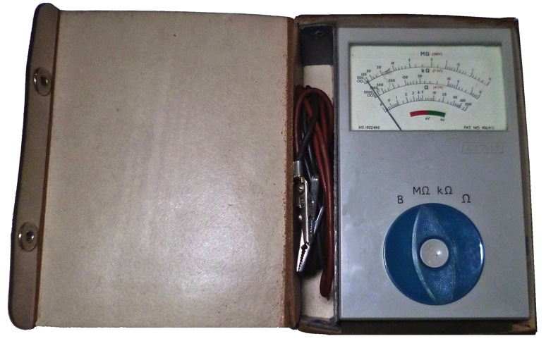
Cat No 40022 (BM6) Serial No 1922490
Evershed & Vignoles Battery Megger tester complete with
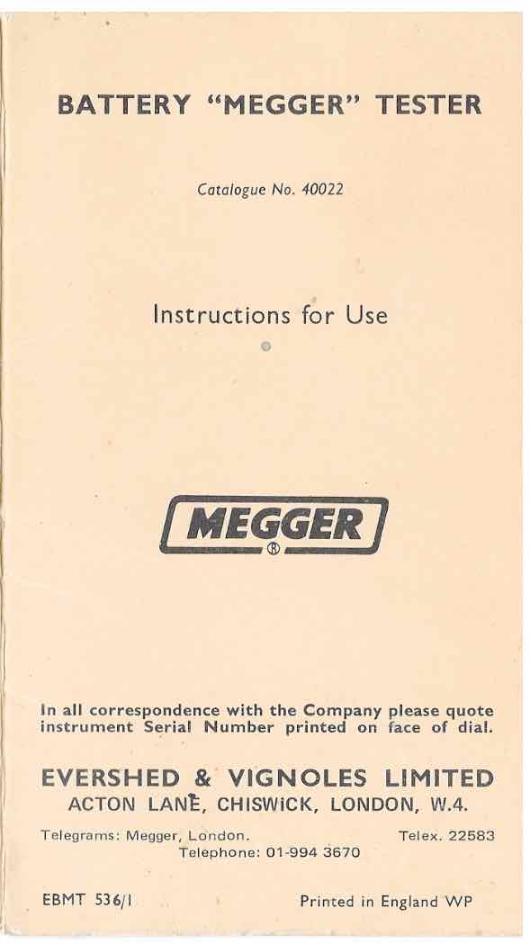
leads, instruction leaflet, leather case and strap. Click on leaflet
image to download PDF. This is
one of the earliest versions of battery operated portable combined
continuity and insulation testers made by
E&V. The concept of this instrument is similar to this one in my collection dating from
about 1962 although it does not include the facility to measure
voltages. Both incorporate features of GB patent 956913 of 1962. I am
guessing that this one dates from 1966/7 which is about the time that
ACY21 transistors became available. Later versions of this model
designated BM6 made
in the Dover factory have a blue label for the switch markings like the
BM7 and BM8 models which have conventional single taut band suspension
moving coil meter
movements. The move to the Dover factory was in 1986 though I believe
some instruments were assembled there prior to this.
These MEGGER testers are suitable for single voltage insulation
resistance and continuity testing on domestic wiring systems and
equipment, transformers, motors and generators. The BM6, BM7-500 and
BMV7 mk2 are suitable for testing that 240V installations comply with
British IEE Wiring Regulations. The BM7-250 model is suitable for 120V
installations. The BMV7 also measures a.c. voltage up to 500V.
BM6 (cat 40022)
This instrument operates over three ranges, 0-2OOMΩ for
insulation testing at 500V d.c., 0- 5000kΩ for resistance and
continuity testing at 8,5V d.c., and low voltage continuity testing at
5,5V d.c. over the range 0-200Ω. The 500V test voltage is derived from
a transistor oscillator, powered by six, 1,5V HP7 dry cells. The
Evershed cross-coils movement
requires no setting-up or adjusting, and is individually calibrated.
BM7-250 and BM7-500 (cat 40051
and cat 40050)
The BM7-250 is intended for low voltage tests, operating at a
test voltage of 250V. The BM7-500 tests at 500V. The test voltages are
generated only when the test button is pressed and there is a built-in
battery check position. The instrument is housed in a lightweight,
rugged case, and has a taut band
suspension, moving coil movement. The BM7 models probably date
from the early 1970s.
BM8 (cat 40060)
This is a later model intended to be more versatile and having test
voltages more suitable for telecommunication and electronics testing.
The BM8 models probably date from the early 1980s. The BM8 Mk2 is a
much later version dating from the late 1990s.
BM10
Test voltages available include 50, 100, 250, 500, 1000 V DC.
Measurement range to 100 Gigaohm. Continuity range 0.1 to 200 ohms.
AC/DC voltage range 500 V. This instrument has a conventional moving
coil metyer movement. Battery 4x1.5V cells (type C).
Service Manual can be downloaded here

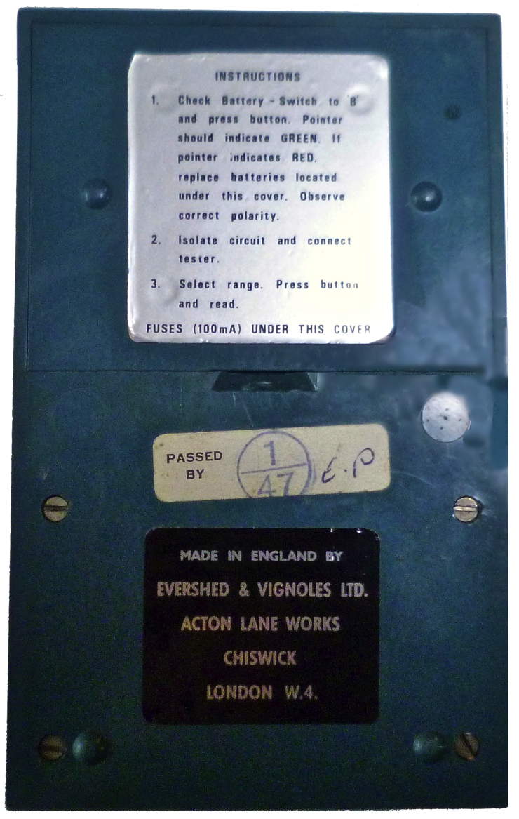
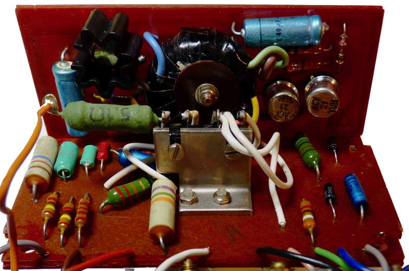
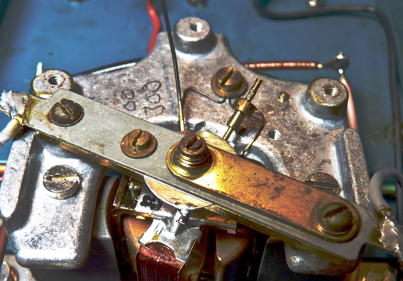
The instrument has a 500 V DC two transistor (ACY21) inverter
which can be seen on the right of the vertical section of the component
boards. It is powered by six 1.5 Volt size AA cells and incorporates a
two coil meter movement similar to that used for many
years in their continuity testers
This instrument (Cat 4022) and the cat 40050/40051 are externally
different to the BM6, BM7 and
subsequent models made by
Evershed and Vignoles at the Megger Instruments Division in
Dover illustrated here. The BM7 models probably date from the early
1970s.The same outward construction was also used for the LT3 mains
powered ohmmeter used for determining the line-earth resistance of
mains power supplies see here
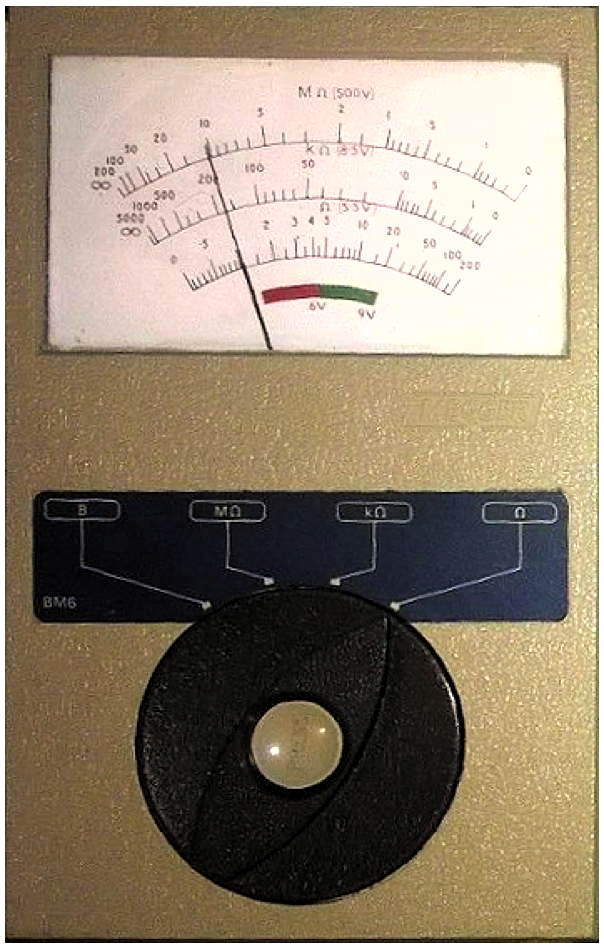
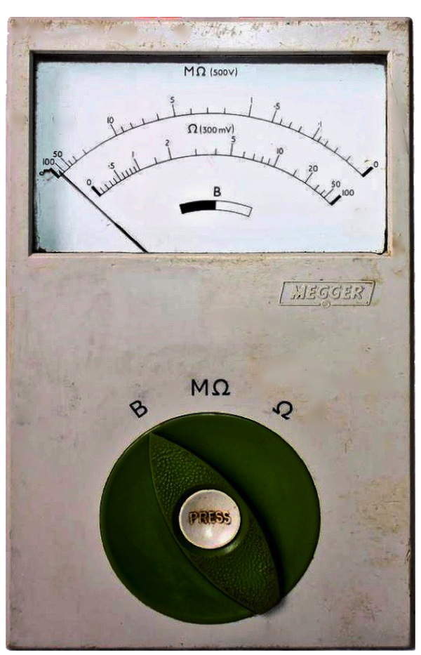
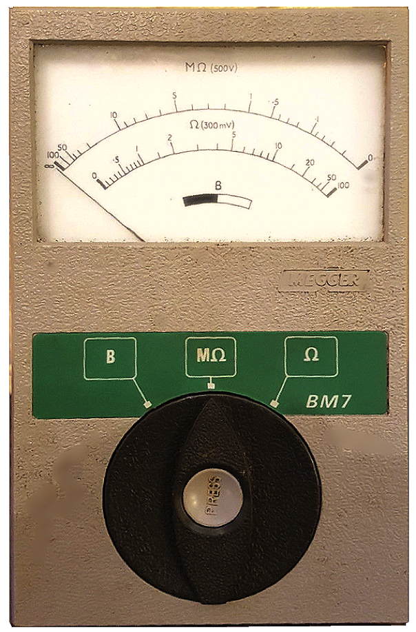
Left to Right BM6,
cat 40050, BM7 and PO19C (made for British Telecom)
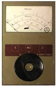

BMV7 Mk2 (cat 40075)
and BM8 Mk2
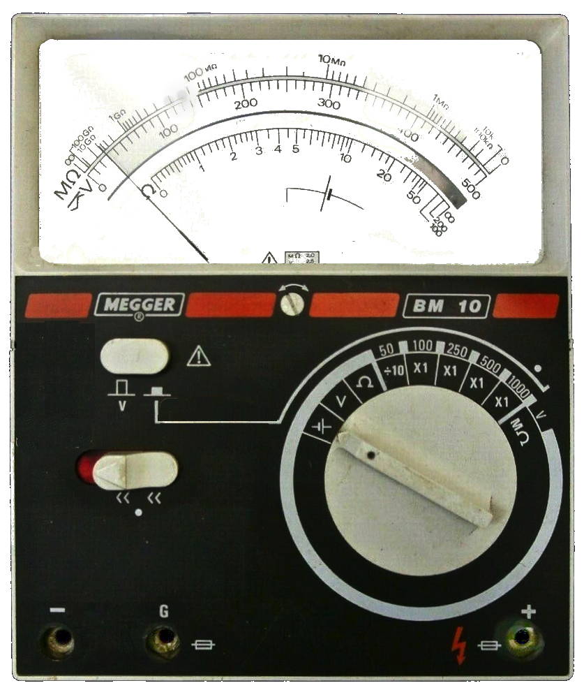
BM10
dates from about 1990
An intrinsically safe version of the
battery Megger tester utilising a crossed coil meter movement was also
manufactured (cat 40044) during the mid 1960s.
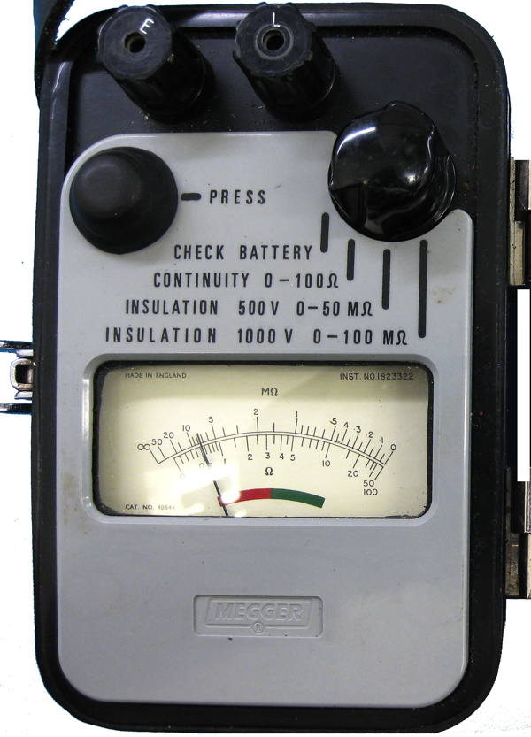
How does the two coil instrument
work?
The moving system consists of two coils, the "control
coil" and the "deflecting coil" rigidly mounted at an angle to one
another and connected, in parallel across a DC voltage supply, with
polarities such that the torques produced by them are in opposition.
The coils move in the air gap of a permanent magnet. The control coil
is in series with a fixed control circuit; the deflecting coil is
connected in series with a fixed deflecting circuit resistance and the
resistance under test. If this last is infinitely high no current flows
in the deflecting coil and the control coil sets itself perpendicular
to the magnetic axis, the pointer indicating "Infinity." A lower test
resistance allows current to flow in the deflecting coil and turns the
movement clockwise. The control torque produces a restoring torque
which progressively increases with the angular deflection, and the
equilibrium position of the movement is attained when the two opposing
torques balance. The main advantage of insulation testers using this
type of movement is the insulation resistance indicated will be correct
even if the the applied voltage is incorrect.
The control coil is actually in two parts, in series,
the outer
part being a compensating coil. The two parts are arranged with numbers
of turns and radii of action such that, for external magnetic fields of
uniform intensity, their torques cancel one another thus giving an
astatic combination.
Other insulation testers work on the same principle though the
voltage required may be obtained from a hand or a
motor driven generator. see this example.
For more information on Evershed and Vignoles early insulation testing
equipment see: here.
Evershed & Vignoles Ltd of Acton Lane Works,Chiswick
were taken over by AVO Ltd. Avocet House, 92-96 Vauxhall Bridge
Road,
London, SW1. AVO was a member of the Metal Industries Group of
companies. Though known for their Avometer general purpose
multimeter
(see below), they made a wide range of test gear including valve
testers. The Acton Lane works closed down at about that time - around
1986. The current range of products can bee seen at: http://www.megger.com
The firm Megger Ltd is now based at: Archcliffe Road, Dover,
Kent,
CT17 9EN, United Kingdom.
For hand driven generators, Meggers and other insulation testers click here


