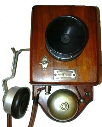
Hunningscone Patent Battery Wall Telephone, comprising: Hunningscone Revolving Granular Carbon Transmitter, Induction Coil, Call Bell, Automatic Switch Hook and Ringing push button. Metal Parts Nickel plated and Woodwork Solid Walnut. original earpieces are missing. I have two of these and they are working.I am looking for two authentic watch receivers, the earpieces you see here are from a pair of Ericcson headphones. UK 1899?

The labels with the magnet trademark seem to indicate that they were made by Peel Conner:

One of these telephones is marked on the back in pencil with "31-7-99" and appear to be very similar to those shown on:
http://www.britishtelephones.com/gec/k040.htm Peel Conner started business in 1896 at the Telephone Works, Adelphi, Salford, Manchester. UK Subsequently this firm was acquired by GEC in 1910 and it seems that manufacture continued at the Telephone Works in Coventry.
In 1878, Henry Hunnings, an English clergyman who came from Yorkshire, invented a microphone using loosely packed granules of coke between a electrically conducting diaphragm and a metal backplate instead of the tightly packed button of carbon used previously. Sound waves caused the diaphragm to flex, causing the granules to squeeze tightly together and then relax as pressures from the speech sounds changed. The loose granules formed multiple parallel contacts, allowing the microphone to carry higher currents than the single contacts used previously. It was subsequently marketed as the "long distance" transmitter because its higher output and efficiency produced audible transmission over longer lines. Its one drawback was that it had a tendency to "pack" and lose its sensitivity. Occasionally rotating the microphone helps loosen the granules.
The following description is taken from "Electric Bells and Telephones" Bernard E Jones, first published by Cassell & Co. in 1916
Hunnings' Cone or Deckert Transmitter, - Among these, one of the best yet produced is known as the" HunningsCone" or " Deckert" transmitter, in which granulated carbon takes the place of the pivoted pencils used in previous types. This instrument is shown in half section by Fig. 91. In the original form shown the body A and the cover B are of ebonite screwed together. The body is recessed to accommodate the carbon block, which is shown in solid black. This is circular in plan, and has a conical back, to which is attached a brass plate drilled and tapped to receive the screw K, which secures the block within the body, and also provides one of the electrical connections. The circular face of the carbon is corrugated, or rather, studded with small pyramids. Facing the block (but not in contact with it) is a thin disc or diaphragm of carbon D, which beds against a metal ring H, and is secured in position by the screwed ring E banking against the packing ring F of waxed felt or cardboard. Electrical connection with the diaphragm is effected through the recessed metal ring on which it rests by means of the brass rod shown, riveted and soldered thereto. Wires to battery and coil are led from I and K. The cover B has an internal screwed ring to secure the -metal-gauze diaphragm G, the sole function of which is to shield the delicate carbon diaphragm D from accidental damage. The shallow space between the studded block and the carbon diaphragm is filled in with granulated carbon, screened to an equal size, coated with a film of graphite, and' carefully sifted free from dust. These polished, graded, and dustless granules constitute a partial, imperfect, and variable connection between the corrugated back block and the flexible diaphragm facing it. Theoretically it might be assumed that this granule packing must arrest the vibration of the disc under the impact of sound-waves; but practice has proved that even more than sufficient resiliency is retained by the disc (which has, in fact, to be additionally muted or controlled for ordinary telephonic purposes).

Figs 97 and 98 from the same publication reproduced below show the internal connections for a very similar phone. Such a telephone would generally be used for distances of up to a 1500 metres and might use two wires or one wire and an earth return. A battery of two or three Leclanche cells (1.5 volts each cell) would be installed adjacent to each telephone. The positive terminal of such a cell is made of Carbon and the negative of Zinc. Two cells would be used for signalling to operate the bell and one to power the microphone. This latter cell can be omitted if the distance between telephone is less than 100 metres.
The meaning of the lettering on these early telephone now becomes
clear:
L= line
C=carbon i.e. positive
ZE=zinc and earth i.e. negative
MC= microphone and carbon

Here are some connection diagrams for other similar 4 terminal telephones


In 1878 Henry Hunnings in Britain patented
an improved Edison transmitter, which used carbon granules instead of
powder. This gave stronger transmission and reduced packing of the
carbon in the bottom of the transmitter, a well-known problem that
reduced the transmission level (taken from a history of GEC telephone
manufacture see here: http://www.cntr.salford.ac.uk/comms/resources/ISTInnerSpring08GEC.pdf